If you are replacing a component, remove the existing component before performing the installation process.
Steps
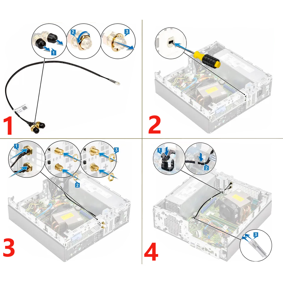
- Remove the fillers on the side cover.
- Tilt the SMA antenna assembly.
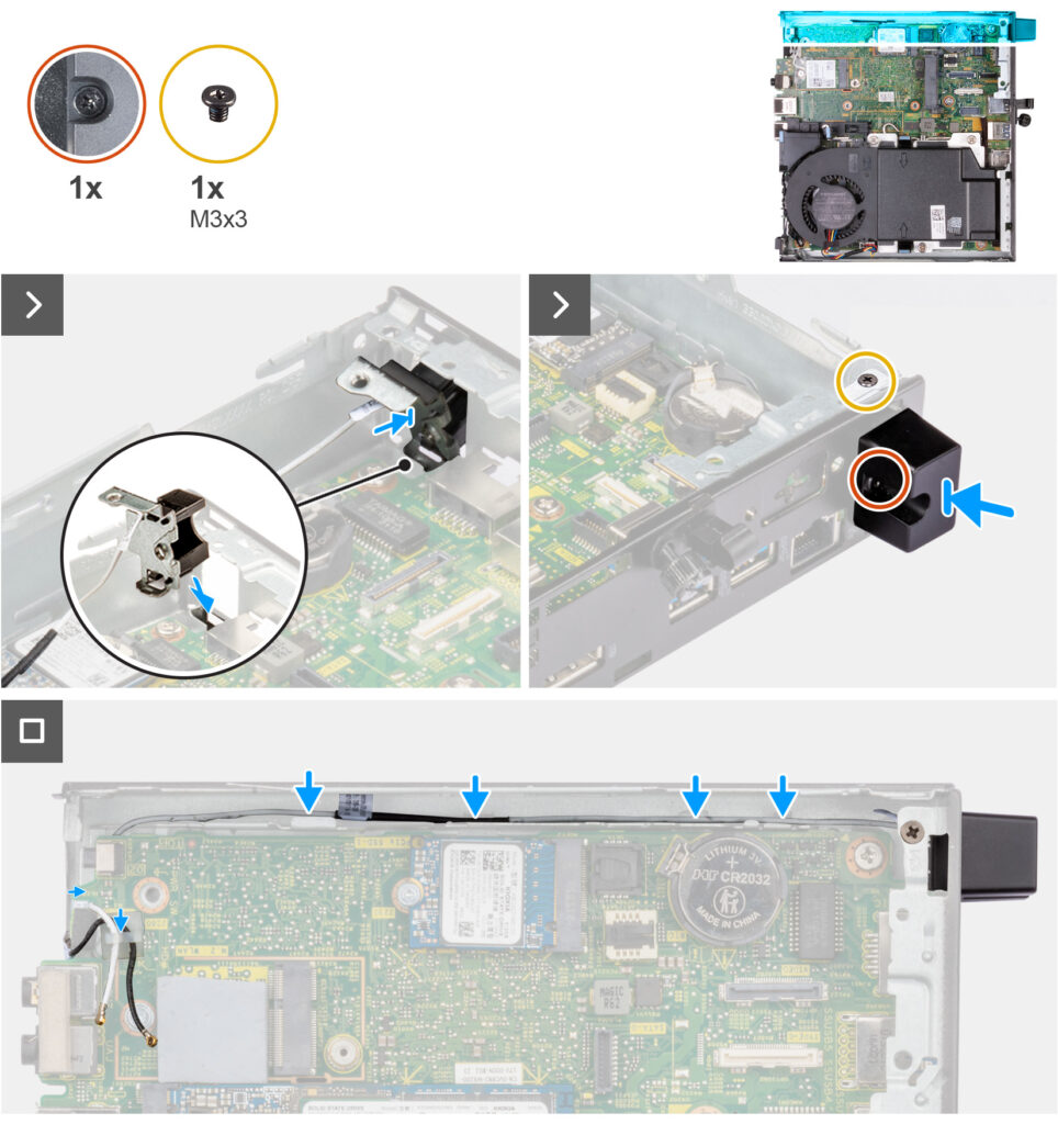
- Align and place the antenna bracket on the system board.
- Insert the SMA antenna assembly in the back view opening.
- Align the screw hole on the SMA antenna assembly with the screw hole on the back view.
- Replace the screw (M3x3) that secures the SMA antenna assembly to the chassis.
- Route the SMA antenna assembly cables through the routing guides on the chassis.